It is important to avoid lifts in vacuum return lines whenever possible. Under no circumstances should lift fittings be used in lieu of an auxiliary accumulator tank in the return main at the inlet to the vacuum heating pump receiver. When there is no practical way to avoid a lift out in the system, the inherent disadvantages may be minimized by the proper selection and careful installation of the required lift fittings.
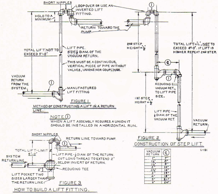
The operating principles of a lift may be described by referring to Figure (1) above. Condensate flows by gravity and accumulates in the well of the lower lift fitting thus sealing the base of the vertical lift pipe. The water seal interrupts the flow of air in the return line with a result that the vacuum decreases in the lower section. Thus a pressure differential is created between the lower and upper sections of the return line. It is this pressure differential that provides the motive force required to raise or “lift” the condensate to the upper line. Once lifted to the upper line, water is prevented from dropping back by the upper loopover.
In operation the lift works with a pulsating action alternately lifting slugs of condensate, then as the seal is momentarily broken, slugs of air and water vapor. The action is sufficiently rapid to mix the condensate and air. At the start of the lift action a pressure differential of about 1/2lb. (or 1 inch of mercury vacuum) is required to lift the water for each foot of vertical rise. As the cycle proceeds, the condensate and air become mixed and the density of the mixture is less than for water alone. Under this condition, the required pressure differential is reduced about 60 per cent of all above values. In spite of this reduced density, the pressure loss in the lift should be calculated upon the basis of a solid column of water.
Figure (1) shows a single step lift which will meet usual requirements. Note that in place of the loopover at the top of the lift, a manufactured lift fitting may be used if preferred. Based on practical experience, the single step lift should be limited to 5 feet. It should also be emphasized that the lift must be deducted from the vacuum that can be maintained in the low section of the return line. For example, assume that a vacuum of 10 inches is maintained in the upper section by the vacuum heating pump. Then if the lift is 5 feet, it follows that a vacuum of only 5 inches can be maintained in the lower section of the return line.
Figure (2) shows a two step lift which may be used to handle a lift greater than 5 feet, but not exceeding 8 feet. By breaking the lift into two equal steps, the lift takes place first in one step, then in the other, so that the effect is cumulative. Thus the loss in vacuum for an 8 foot, two step lift, is about the same as a 5 foot, single step lift. Due to the additional friction losses, the twp step lift is not as efficient as the single step lift.
Lift fittings as made by the steam specialty manufacturers are preferable because they can be installed with a minimum cost for labor. However, such fittings may not be readily available when needed. In such case, satisfactory lift connections can be made from standard pipe fittings on the job. Figure (3) shows the proper design and dimensions for lift connections. The design and dimensions should be followed closely.
Mechanical Lifts
A condensation pump may be used as a mechanical lift in lieu of a vacuum lift whenever it is desired to return condensate from a location that would not otherwise gravity drain to the vacuum heating pump.
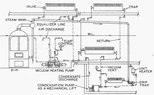
The drawing above illustrates this concept. Mechanical lifts like this may also be used out in the system instead of a vacuum lift whenever a positive means of moving condensate is needed. Another example is a mechanical lift instead of a door loop when underground wet return piping is not desired.
When a condensate pump is used as a mechanical lift in a vacuum system, it is MOST IMPORTANT that the condensate pump and receiver be air tight and suitable for vacuum service. Also, the condensate pump’s air vent must be piped to a vacuum return, and NOT JUST TO ATMOSPHERE. This ensures the benefit of a vacuum return are applied to the entire heating system. It is also recommended that a pressure vent check valve be installed in the vacuum vent line to vent off any positive pressure that might develop.
